This blogpost originally appeared on member Eugenio Pace’s website and has been modified for presentation here.
My model railway club (ETE) is building a few new modules for our layout. One of them features a brewery, based on this kit from Faller. It’s a detailed model, and we’re lucky to have Alan—an expert diorama builder—bringing it to life. Great work, Alan!
The bottling section is motorized, with rotating carousels of bottles, and the building includes simple yet effective lighting.
One great feature of successful layouts—especially for younger visitors—is interactivity. Think Miniatur Wunderland style. Inspired by them, I set out to build a simple module triggered by a strategically placed button on the edge of the layout. When pressed, the carousels start rotating, the lights turn on, and the sounds of a bottling plant begin playing: movement, sound, and lights. After a predetermined amount of time, everything shuts down—ready for the next press of the button.
A fellow club member mentioned the excellent BBC Sound Effects Library—a treasure trove of audio clips worth exploring.
Before using BBC clips, make sure to review their licensing terms.
I’ve had good results with the Adafruit VS1053 audio board, so sound playback was the easy part. Adafruit also makes a handy “relay shield.” With both boards, I had the basic components needed to animate the brewery.
In addition to the push button, we also wanted to activate everything remotely, integrating into the layout automation that our resident electronics expert, Jan, has been working on. He introduced me to the CBUS specification from MERG, which, fortunately, is based on a standard communications protocol: CAN. I picked up an Adafruit CAN controller and added it to the mix. CBUS allows us to control the module centrally—while still supporting local button presses.
Hardware
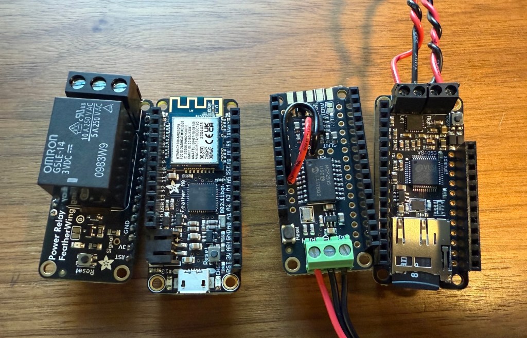
I’m using four main boards:
- Relay “shield” – Simple relay board, controlled with one I/O pin.
- Feather M0 WiFi board – This is the main microcontroller. It’s based on ARM’s Cortex M0 processor—a solid microcontroller with great peripheral support. I won’t be using Wi-Fi initially, but it’s there if needed.
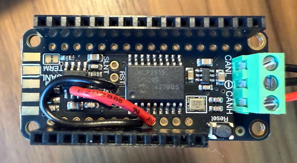
- CAN bus controller – Based on the battle-tested MCP2515 chip.
- VS1053 audio board – It includes a built-in SD card slot and an onboard amplifier. The SD card will store the audio tracks and other information (like error logs and configuration).
The VS1053 board has fixed pin assignments, but the relay and CAN boards allow pin remapping—making stacking simple.
Pin Configuration
| Device | Function | I/O pin | Config | Notes |
| Relay | Activate Relay | 11 | Output | The relay can handle 250V / 5 A—plenty for this app. |
| Audio Data CS | Chip select for audio data | 6 | Output | VS1053 uses separate SPI buses. |
| Audio Control CS | Chip select for audio commands | 10 | Output | |
| SD CS | Chip select for SD card | 5 | Output | Shares the board with the audio module. |
| Audio DREQ | Interrupt for Audio | 9 | Input | |
| CAN CS | Chip select for CAN | 12 | Output | |
| CAN INT | CAN interrupt pin | 13 | Input | Not used in this prototype. |
| Push Button | Push button | 14 | Input | Configured with an internal pull-up. |
Only the CAN board required reassigning default pins (due to conflicts), but it conveniently includes jumpers and breakout holes for both Audio Data CS and DREQ:
Sound Board Wiring and Speakers
The VS1053 board includes a built-in amplifier, so connecting speakers is straightforward—just keep within spec: 4–8Ω, 3W. This should be enough for this application.
It supports synchronous operation, but background playback via a hardware interrupt is much smoother. While sounds are playing, you can have the board respond to other commands or inputs. The Adafruit library handles this well. Since SD card access during sound playback can be tricky, I simply disable SD access while audio is active.
CAN Wiring and the CBUS Specification
CAN is a 3-wire bus, designed for long-distance, electrically noisy environments. It’s common in industrial and automotive settings, and not surprisingly, it’s used for layout automation as well.
OBD-II—the standard for car diagnostics—is built on CAN.
CBUS is a protocol created and maintained by MERG (Model Electronic Railway Group) to control model railway layouts.
MERG is an international, UK-based society focused on electronics and computing in model railroading.
Their documentation is excellent and worth reading.
In CBUS, systems are made up of producers and consumers of events. Events originate from a node, and both nodes and events are identified by 16-bit numbers—allowing up to 65,535 nodes and 65,535 events per node, which translates into over 4 billion combinations…enough for a very complex configuration and lots and lots of accessories. What each event means is up to the consumer.
Accessory control (like lights, motors, sounds) is done with two CBUS commands: ACON (Accessory On) and ACOF (Accessory Off), using this format:
| Byte 1 | Bytes 2–3 | Bytes 4–5 |
| Opcode | Node Number (Hi/Lo) | Event Number (Hi/Lo) |
The ACON and ACOF opcodes are standard, with respective values of 0x90 and 0x91.
This simple architecture can support very complex layouts. And, by nature of this design, a single event can trigger multiple actions on multiple consumers.
In this project, my module will act as a consumer. One event will trigger the relay (for the motor/lights), and others will trigger different audio clips from the SD card.
Example:
| Node Number | Event Number | Action |
| 128 | 1 | Relay |
| 128 | 2 | steam.mp3 |
| 128 | 3 | bottling.mp3 |
So, an ACON command from node 128 and event 1 will activate the relay and as a consequence, whatever is connected to it: lights, motors, etc. And and ACON command from node 128 and event 2 will play the steam.mp3 file.
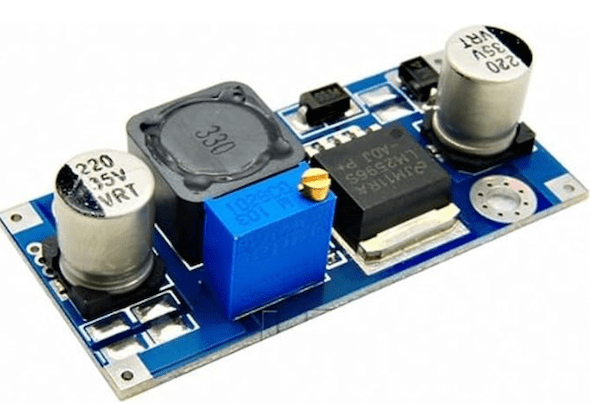
Power Supply
The last component is power. Our layout has 19V DC available everywhere (which provides enough power while remaining safe for everyone and everything). All I need is a converter from 19V to 5V, plugged into the micro-USB connector of the Feather M0. I’ve used boards like this one before with success. They are cheap and effective:
In Part II, I’ll cover the software architecture that brings it all to life.

Leave a comment